MRF8S21140HR3 MRF8S21140HSR3�
� 1�
� RF Device Data�
� Freescale Semiconductor�
� RF Power Field Effect Transistors�
� N-Channel Enhancement-Mode Lateral MOSFETs�
� Designed for W-CDMA and LTE base station applications with frequencies�
� from 2110 to 2170 MHz. Can be used in Class AB and Class C for all typical�
� cellular base station modulation formats.�
� ?�
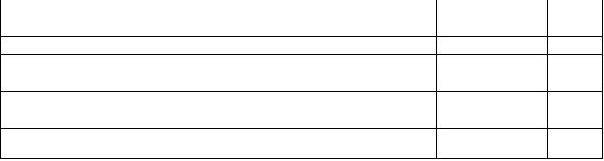
� Typical Single-Carrier W-CDMA Performance: VDD�
� = 28 Volts, I�
� DQ�
� =�
� 970�
� mA,�
� Pout�
� = 34 Watts Avg., IQ Magnitude Clipping, Channel �
� Bandwidth = 3.84�
� MHz, Input Signal PAR = 7.5�
� dB @ 0.01% Probability�
� on CCDF.�
� Frequency�
� Gps�
� (dB)�
� D�
� (%)�
� Output PAR�
� (dB)�
� ACPR�
� (dBc)�
� 2110 MHz�
� 17.7�
� 32.1�
� 6.2�
� -37.0�
� 2140 MHz�
� 17.9�
� 31.7�
� 6.4�
� -37.5�
� 2170 MHz�
� 18.1�
� 31.7�
� 6.4�
� -37.5�
� ?�
� Capable of Handling 10:1 VSWR, @ 32 Vdc, 2140 MHz, 188 Watts CW (1)�
� Output Power (3 dB Input Overdrive from Rated Pout)�
� ?�
� Typical Pout�
� @ 1 dB Compression Point �
� �
� 126 Watts CW�
� Features�
� ?�
� 100% PAR Tested for Guaranteed Output Power Capability�
� ?�
� Characterized with Series Equivalent Large-Signal Impedance Parameters�
� and Common Source S-Parameters�
� ?�
� Internally Matched for Ease of Use�
� ?�
� Integrated ESD Protection�
� ?�
� Greater Negative Gate-Source Voltage Range for Improved Class C�
� Operation�
� ?�
� Designed for Digital Predistortion Error Correction Systems�
� ?�
� Optimized for Doherty Applications�
� ?�
� RoHS Compliant�
� ?�
� In Tape and Reel. R3 Suffix = 250 Units per 56 mm, 13 inch Reel.�
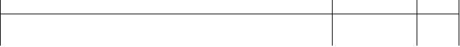
� Table 1. Maximum Ratings�
� Rating�
� Symbol�
� Value�
� Unit�
� Drain-Source Voltage�
� VDSS�
� -0.5, +65�
� Vdc�
� Gate-Source Voltage�
� VGS�
� -6.0, +10�
� Vdc�
� Operating Voltage�
� VDD�
� 32, +0�
� Vdc�
� Storage Temperature Range�
� Tstg�
� -65 to +150�
� °C�
� Case Operating Temperature�
� TC�
� 150�
� °C�
� Operating Junction Temperature (2,3)�
� TJ�
� 225�
� °C�
� CW Operation @ TC�
� = 25�
� °C�
� Derate above 25°C�
� CW�
� 168�
� 0.86�
� W�
� W/°C�
� Table 2. Thermal Characteristics�
� Characteristic�
� Symbol�
� Value (3,4)�
� Unit�
� Thermal Resistance, Junction to Case�
� Case Temperature 75°C, 34 W CW, 28 Vdc, IDQ�
� = 970 mA, 2140 MHz�
� (1), 28 Vdc, IDQ�
� = 970 mA, 2140 MHz�
� Case Temperature 80°C, 150 W CW�
� RθJC�
� 0.47�
� 0.42�
� °C/W�
� Exceeds recommended operating conditions. See CW operation data in Maximum Ratings table.�
� Continuous use at maximum temperature will affect MTTF.�
� MTTF calculator available at http://www.freescale.com/rf�
� . Select Software & Tools/Development Tools/Calculators to access MTTF�
� calculators by product.�
� Refer to AN1955, �
� Thermal Measurement Methodology of RF Power Amplifiers. Go to http://www.freescale.com/rf. �
� Select Documentation/Application Notes - AN1955.�
� Document Number: MRF8S21140H�
� Rev. 0, 5/2010�
� Freescale Semiconductor�
� Technical Data�
� 2110-2170 MHz, 34 W AVG., 28 V�
� W-CDMA, LTE�
� LATERAL N-CHANNEL�
� RF POWER MOSFETs�
� MRF8S21140HR3�
� MRF8S21140HSR3�
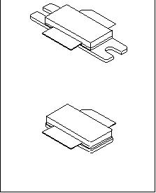
� CASE 465A-06, STYLE 1�
� NI-780S�
� MRF8S21140HSR3�
� CASE 465-06, STYLE 1�
� NI-780�
� MRF8S21140HR3�
� ?�
� Freescale Semiconductor, Inc., 2010. All rights reserved.�
�  �
�
� � �  �
�
� � �  �
�
� � �  �
�
� � �  �
�
� � �  �
�
� � �  �
�
� � �  �
�
� � �  �
�
� � �  �
�
� � 发布紧急采购,3分钟左右您将得到回复。
相关PDF资料
MRF8S21200HSR6
MOSFET RF N-CH 48W NI-1230HS
MRF8S23120HSR5
MOSFET RF N-CH 120W NI-780S
MRF8S26120HSR3
FET RF N-CH 2.6GHZ 28V NI780S
MRF8S7170NR3
FET RF N-CH 700MHZ 28V OM780-2
MRF8S9100HSR5
MOSFET RF N-CH 100W NI-780S
MRF8S9120NR3
FET RF N-CH 900MHZ QM780-2
MRF8S9170NR3
FET RF N-CH 900MHZ 28V OM780-2
MRF8S9200NR3
MOSFET RF N-CH 58W OM780-2
相关代理商/技术参数
MRF8S21140HSR5
功能描述:射频MOSFET电源晶体管 HV8 2GHZ 140W NI780S RoHS:否 制造商:Freescale Semiconductor 配置:Single 晶体管极性: 频率:1800 MHz to 2000 MHz 增益:27 dB 输出功率:100 W 汲极/源极击穿电压: 漏极连续电流: 闸/源击穿电压: 最大工作温度: 封装 / 箱体:NI-780-4 封装:Tray
MRF8S21172HR3
功能描述:射频MOSFET电源晶体管 HV8 2.1GHZ 42W NI780H RoHS:否 制造商:Freescale Semiconductor 配置:Single 晶体管极性: 频率:1800 MHz to 2000 MHz 增益:27 dB 输出功率:100 W 汲极/源极击穿电压: 漏极连续电流: 闸/源击穿电压: 最大工作温度: 封装 / 箱体:NI-780-4 封装:Tray
MRF8S21172HR3_12
制造商:FREESCALE 制造商全称:Freescale Semiconductor, Inc 功能描述:RF Power Field Effect Transistors
MRF8S21172HR5
功能描述:射频MOSFET电源晶体管 HV8 2.1GHZ 42W NI780H RoHS:否 制造商:Freescale Semiconductor 配置:Single 晶体管极性: 频率:1800 MHz to 2000 MHz 增益:27 dB 输出功率:100 W 汲极/源极击穿电压: 漏极连续电流: 闸/源击穿电压: 最大工作温度: 封装 / 箱体:NI-780-4 封装:Tray
MRF8S21172HSR3
功能描述:射频MOSFET电源晶体管 HV8 2.1GHZ 42W NI780HS RoHS:否 制造商:Freescale Semiconductor 配置:Single 晶体管极性: 频率:1800 MHz to 2000 MHz 增益:27 dB 输出功率:100 W 汲极/源极击穿电压: 漏极连续电流: 闸/源击穿电压: 最大工作温度: 封装 / 箱体:NI-780-4 封装:Tray
MRF8S21172HSR5
功能描述:射频MOSFET电源晶体管 HV8 2.1GHZ 42W NI780H RoHS:否 制造商:Freescale Semiconductor 配置:Single 晶体管极性: 频率:1800 MHz to 2000 MHz 增益:27 dB 输出功率:100 W 汲极/源极击穿电压: 漏极连续电流: 闸/源击穿电压: 最大工作温度: 封装 / 箱体:NI-780-4 封装:Tray
MRF8S21200HR5
功能描述:射频无线杂项 HV8 2.1GHZ 48W NI1230HS RoHS:否 制造商:Texas Instruments 工作频率:112 kHz to 205 kHz 电源电压-最大:3.6 V 电源电压-最小:3 V 电源电流:8 mA 最大功率耗散: 工作温度范围:- 40 C to + 110 C 封装 / 箱体:VQFN-48 封装:Reel
MRF8S21200HR6
功能描述:射频无线杂项 HV8 2.1GHZ 48W NI1230HS RoHS:否 制造商:Texas Instruments 工作频率:112 kHz to 205 kHz 电源电压-最大:3.6 V 电源电压-最小:3 V 电源电流:8 mA 最大功率耗散: 工作温度范围:- 40 C to + 110 C 封装 / 箱体:VQFN-48 封装:Reel